ECU Wiring Diagrams
The wiring for the different ecu levels are very similar with all the power output and input pins staying the same. The differences are with the extra features added to the later cars for things like closed loop lambda control, knock sensing and air conditioning.
Level 1 ecu
The level 1 ecu uses pin 12 as an output to drive a engine management fault light via a relay. The fault codes themselves are accessed via the test connector on pins 8 & 27. Grounding either / both the octane inputs on pins 13 & 14 will result in the ignition being retarded by 2,4 or 8 degrees. The MAP sensor wires are fully screened back to the ecu to prevent electrical noise affecting the mixture.
Level 6 ecu
The level 6 ecu is wired the same as the level 1 ecu except the engine management fault light is no longer implemented. Actual fault codes are still available from the test connector obviously.
Level 8 & P8 ecu
The level 8 ecu uses pin 12 output to drive the air conditioning clutch so that it disengages under WOT. It has the ISCV power feed moved to the ecu relay rather than the fuel pump relay probably in readiness for the P8 ecu which uses a self cleaning software routine which will pulse the valve fully open for a few seconds before the engine is started. The TPS +5v supply is reversed to create a voltage which increases with throttle opening.
The only wiring difference between the L8 and the P8 is that the P8 loom has pin 9 (which is an aux input) connected to +5v via pin 30.
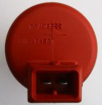
The ISCV may have a picture of a diode on it like the one shown above. In this case the polarity of the connections to it are very important to prevent a short circuit, as reversing the connection will cause the ecu to directly connect ground to +12v through the forward conducting diode. The purpose of the diode is to clamp the ecu side to a maximum of battery voltage + 0.6 Volts when the ecu transistor turns off rapidly.
The left pin (marked -) needs to be connected to the ecu output and the right pin (marked +) needs to be connected to the main +12v feed.
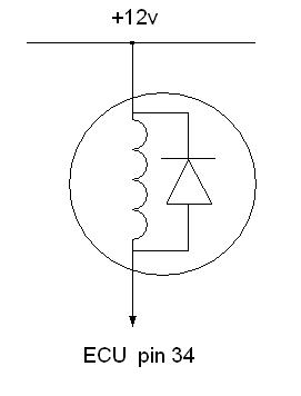
The ecu itself also contains a diode so it doesn't matter if the ISCV doesn't have one built in.
All sierra cosworth models used a loom which was separate from the car loom, so it is easy to remove it and use in a different application. The 4x4 L8 differs from the earlier ones in that it is a two part loom with an engine section and a scuttle to ecu section allowing the engine to be removed with its loom still attached. On all types there are basically just 5 wires to connect up :-
ground = brown
battery = red or red/blue
ignition switch = black
fuel pump = black/red
rev counter = green
The brown/green wire is not required as it is for the fault light relay on the L1 or the air con on the L8.
ECU Connections summary table :-
PIN |
LEVEL 1 |
LEVEL 6 |
LEVEL 8 & P8 |
|---|---|---|---|
| 1 | GROUND | GROUND | GROUND |
| 2 | N/C | N/C | LAMBDA SENSOR |
| 3 | CRANK SENSOR -VE | CRANK SENSOR -VE | CRANK SENSOR -VE |
| 4 | CRANK SENSOR +VE | CRANK SENSOR +VE | CRANK SENSOR +VE |
| 5 | PHASE SENSOR -VE | PHASE SENSOR -VE | PHASE SENSOR -VE |
| 6 | N/C | N/C | KNOCK SENSOR |
| 7 | N/C | N/C | CARBON CANISTER PURGE |
| 8 | DIAGNOSTIC INPUT | DIAGNOSTIC INPUT | DIAGNOSTIC INPUT |
| 9 | N/C | ||
| 10 | ECU POWER RELAY DRIVE | ECU POWER RELAY DRIVE | ECU POWER RELAY DRIVE |
| 11 | SENSORS GROUND | SENSORS GROUND | SENSORS GROUND |
| 12 | FAULT LIGHT RELAY DRIVE | N/C | AIRCON CLUTCH RELAY DRIVE |
| 13 | OCTANE ADJUST | OCTANE ADJUST | OCTANE ADJUST |
| 14 | OCTANE ADJUST | OCTANE ADJUST | OCTANE ADJUST |
| 15 | MAP SENSOR | MAP SENSOR | MAP SENSOR |
| 16 | AMAL BOOST VALVE | AMAL BOOST VALVE | AMAL BOOST VALVE |
| 17 | TPS | TPS | TPS |
| 18 | INJECTOR CYL 4 | INJECTOR CYL 4 | INJECTOR CYL 4 |
| 19 | GROUND | GROUND | GROUND |
| 20 | ECU +12V POWER | ECU +12V POWER | ECU +12V POWER |
| 21 | N/C | N/C | AIRCON SENSE INPUT |
| 22 | N/C | N/C | KNOCK SENSOR |
| 23 | PHASE SENSOR +VE | PHASE SENSOR +VE | PHASE SENSOR +VE |
| 24 | IGNITION MODULE -VE | IGNITION MODULE -VE | IGNITION MODULE -VE |
| 25 | IGNITION MODULE +VE | IGNITION MODULE +VE | IGNITION MODULE +VE |
| 26 | N/C | N/C | N/C |
| 27 | DIAGNOSTIC OUTPUT | DIAGNOSTIC OUTPUT | DIAGNOSTIC OUTPUT |
| 28 | FUEL PUMP RELAY DRIVE | FUEL PUMP RELAY DRIVE | FUEL PUMP RELAY DRIVE |
| 29 | ECT | ECT | ECT |
| 30 | SENSOR 5V | SENSOR 5V | SENSOR 5V |
| 31 | ACT | ACT | ACT |
| 32 | INJECTOR CYL 2 | INJECTOR CYL 2 | INJECTOR CYL 2 |
| 33 | INJECTOR CYL 3 | INJECTOR CYL 3 | INJECTOR CYL 3 |
| 34 | ISCV | ISCV | ISCV |
| 35 | INJECTOR CYL 1 | INJECTOR CYL 1 | INJECTOR CYL 1 |