Hardware
The heart of the ecu is the MC6803U4 micro controller running at 1Mhz from a 4Mhz crystal. This is made to work in mode 2 by forcing pin 8 low and pin 9 high at reset.Mode 2 enables the internal RAM and a multiplexed external bus. If the pins are not in the correct state it will lock up in a continuous loop until reset.
Any glitches which may force the program to crash during normal running will be captured by the external watchdog timer. This will reset the micro in < 100 mS if it is not regularly reset by the micro itself. Pin 17 of the micro is used to turn the fuel pump on/off and is also regularly pulsed at high speed by software. This pulse is too fast for the fuel pump to see but is enough to reset the watchdog timer. If the software ever crashes then the watchdog timer will time out and reset the micro. This may or may not cause an engine stall.
The program itself is stored in an 8KB EPROM (16KB on the L8). The L8 also has an extra 2KB RAM to store the extra variables required by its more complex program as it has the ability to control engine knock, closed loop running with an oxygen sensor, carbon canister etc. The program completely fills the 8KB EPROM but there is a lot of free space in the 16KB. The L1-L8 ecus all use the same micro controller and clock speed so there is no difference in performance between the types.
INPUTS
The engine position is determined by two inductive sensors detecting metal lugs on the crank pulley and the distributor shaft. Each sensor produces a positive / negative cycle as the lug passes which is converted by a zero crossing module into a 5v digital pulse which can be used by the micro.
For sequential injection to work, the engine needs to know not just where tdc is, but also which cycle it is on. Hence the need for two sensors - the crank sensor and the phase sensor. The crank sensor detects 4 lugs on the crank front pulley spaced 90 degrees apart. These are used to calculate engine speed and when to start the ignition / injection timers. The phase sensor is in the base of the distributor and has only 2 lugs spaced 90 degrees apart (180 crank degrees) and their sequence in relation to the crank pulses lets the ecu know the engines exact position.
OUTPUTS
The injectors are driven sequentially rather than batch fired so each has its own driver circuit fed by its own programmable 16 bit timer. Three timers are contained in the 6840 ic and one in the micro itself. The 6840 timers are clocked at 250KHz and the micro one at 1Mhz which means that on long injection times the micro timer can overflow 3 times and requires extra software to service it. FFFF @ 250KHz gives a max injection period of 262mS which would only ever be required for cold cranking in arctic conditions. The injectors are of the low impedance (2.5 ohm) type for fast response and would burn out if driven directly from 12V so each has its own current limiting driver consisting of half a sealed module and a BDX53M transistor.
An injector requires less current to hold it open than it does to get it to open in the first place, so the drivers used are of the peak hold type where the injector is allowed the full 12v for about 1.4mS up to 2.3A to get them to open quickly and then the driver limits the current to 0.6A until the end of the injection period. This reduces power consumption, heat and enables it to close quicker. When the injector voltage is reduced / turned off the inductance of the injector creates a voltage spike which is limited to 68V by a zener diode.
The picture on right shows the standard weber injector for the early cosworths. It has a yellow top and flows 311cc/min which is enough for approx 270bhp. Later cosworths had the same injector but with a dark blue top, a change which was made around the time Ford colour coded under bonnet service parts yellow and didn't want to confuse people. There are a number of injector upgrades which allow the engine to produce over 270bhp with correct fueling under full power, but the idle mixture will become harder to control when the flow rates become very large as the opening times become proportionally shorter.
0280 150 803 = dark greens 382cc/min - up to approx 350bhp
0280 150 400 = light blue 437cc/min - up to approx 380bhp
0280 150 403 = grey 503cc/min - up to approx 440bhp
The ecu also contains another two BDX53M transistors which are used to drive the Amal valve and the idle speed control valve. Both use pulse width modulation to control the amount they are opened by.
 The Amal valve (shown right) uses a fixed frequency of 10Hz and a pwm varying from 5% - 95%. The more the valve is pulsed open, the more air is directed away from the wastegate actuator through a bleed hole, so the higher the boost pressure becomes. The ecu contains a boost table which varies the pwm depending on rpm and map. If the air charge temperature becomes too high or the rpm is held over 6250rpm then the Amal will be pulsed closed to reduce boost pressure and prevent engine damage.
From left to right the pipes are marked R,C,W
R = Return to air filter
C = Compressor
W = Wastegate

Shown on the right is the underside of the Amal valve.
With no power to the valve the C and W pipes are directly connected, so the wastegate gets the full compressor pressure and will limit boost pressure to approx 0.3 bar (5psi). Fully energizing the valve will bleed off some pressure away from the wastegate and back to the air filter resulting in a boost pressure of approx 0.7bar (10psi). PWM pulsing will allow pressures between these two values. The 4x4 cosworth ran a slightly higher boost pressure than the earlier models to increase power to offset the greater transmission losses and weight. A lot of modified chips bypass the Amal calculations routine so it is permanently fully on, or they totally remove the valve from the car which means the engine cannot reduce boost pressure if it detects a sensor problem or the ACT becomes too high.
The Idle Speed Control Valve (ISCV) is shown on the right. It consists of a big solenoid coil which pulls against a sprung loaded plunger inside a fixed outer sleeve.The greater the current on the coil, the further the plunger is pulled towards it, causing a hole of increasing size to be exposed. The hole itself is shaped so it initially only increases in size slowly, for slight corrections, but then rapidly increases in size for large amounts of air required when a very cold engine is idling. Some ISCV have a diode built into them so the polarity of the wiring is important. On the early cosworths (level 1 & 6) the idle speed is set to 850 rpm using the bypass screw on the throttle body with the ISCV unplugged. The ecu is programmed so that the normal idle speed is also 850 rpm, so really the valve is only actually providing extra air when the engine is cold or the load on the engine increases causing the engine speed drops e.g. an increase in electrical load on the alternator. The level 8 ecu has a 900 rpm idle speed and a more refined control algorithm which takes battery voltage into consideration unlike the earlier ones.
The idle valve uses a fixed frequency of 80Hz and a pwm varying from 10% - 90%. The idle valve pwm is controlled when the throttle is closed to maintain the idle speed between an upper and lower speed depending on engine temperature.
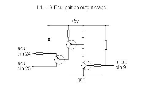
The ignition amplifier module is shown on the right. It contains the high current / voltage transistors required to drive the ignition coil and has a metal back for mounting onto a heat sink to dissipate the heat generated by it. The module has its own 12v feed, and ground, and is only linked to the ecu by two wires - one from pin 24 which is a reference ground and another from pin 25 which is the control line. When pin 25 is low (about 0.3 volts), the module is turned on and will be holding the coil -ve supply low to charge the coil. When pin 25 goes high (about 3.5 volts) the module will turn off and cause the coil to also instantly turn off, causing a spark to be generated. By delaying how long after the spark line 25 stays high, the dwell can be varied to limit unnecessary power losses at low rpm. The actual coil current limiting is still controlled by the module itself though. The signal for pin 25 is generated by a capture compare unit within the micro controller causing an interrupt to instantly change the pins output level when the the timer value matches it. The ecu uses a transistor to buffer the micro output which is either shorting pins 24 to 25 or open circuit and is shown in the circuit diagram below. On the P8 it is easy to implement a second ignition output on pin 26 which, when connected to a second ignition amplifier, can be used to create distributorless ignition. Pin 25 then fires cylinders 2&3 and pin 26 fires cylinders 1&4.
Shown below is the signal from pin 25 of the ecu at varying rpm. At cranking speed the ecu runs a fixed zero degrees of advance and can be seen to produce a double firing pulse. It has to produce a fixed pulse when the crank pulse is detected as it would be impossible to reliably calculate the time to the next 90 degree pulse when the speed is so unstable. Once above 600rpm it starts to use the look up tables for its advance. At higher revs the dwell period (coil power on angle) is increased to keep the spark energy the same as the time available reduces.
The connections for the ignition amplifier are:-
pin 1 = Coil negative pin
pin 2 = Main ground (must be a good, high current link)
pin 3 = Ref ground to pin 24 of ecu
pin 4 = Ignition switch +12v
pin 5 = n/c
pin 6 = Switching signal to pin 25 of ecu
pin 7 = n/c
In the picture above, pin 1 is on the far right.