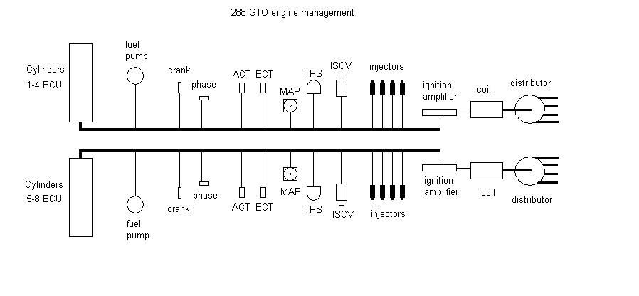
Two of the greatest Ferraris ever made use Weber-Marelli IAW engine management :- The 288 GTO and the F40. Both had V8 engines with flat plane cranks which meant they were really 2 x four cylinder engines linked together. This enabled a pair of 'standard' ecus to manage them, one for each bank.
Ferrari 288 GTO : 1984-1985
ECU = 2 off : IAW 011
2855cc V8
7.6:1 comp ratio
400 bhp @ 7000rpm 366 lb/ft @ 3800rpm
12psi boost with a 15psi overpressure warning light
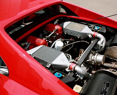
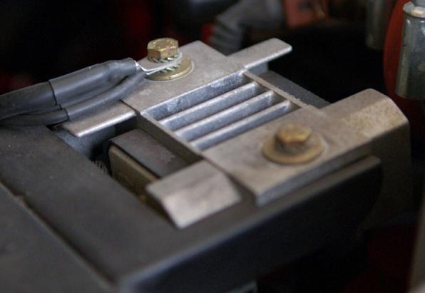
The two ecus are fixed to the engine bulkhead, inside the passenger compartment, behind the drivers and passengers seats. This is a very early IAW ecu which precedes the level 1 with a central screw holding the cover on instead of the normal 4 small screws. By having two ecus with totally separate sensors it is possible to keep running on one cylinder bank even when the other has developed a fault. Both ecus are exactly the same as they use exactly the same inputs and outputs, are running the same program, and are interchangeable side to side for fault finding.
This is very similar to a Ford Cosworth management set up. The two throttles (one per inlet plenum) use the same type of throttle body as the Cosworth with an idle speed control valve built in.
The fuel supply is also treated as two separate systems, with each cylinder bank having its own pump, fuel regulator and fuel rail. The engine has 8 injectors, one per cylinder.
Each bank also has a distributor on the end which contains the phase sensor and the rotor arm to distribute the spark to the correct cylinder.
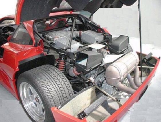
Ferrari F40 : 1987-1992
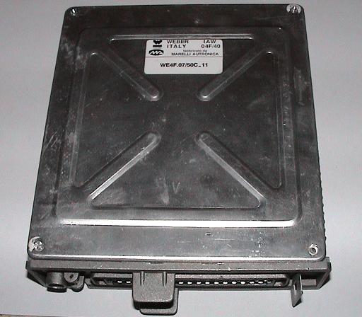
ECU = 2 off: IAW 04F/40 - (WE4F.07/50B.10 or WE4F.07/50C.11)
2936cc V8
7.8:1 comp ratio
478bhp @ 7000rpm 425lb/ft @ 4000rpm
16psi boost with a 22psi overpressure warning light
There are 3 different part numbers of ecu:
142778 which is the US spec F40 with catalytic converters.(Shown above).
134527 which is the European F40 without catalytic converters (case has mounting lugs like a L6 Cosworth)
143401 which is the European F40 with catalytic converters (case has mounting lugs like a L6 Cosworth)
This is an improvement on the earlier system with distributorless ignition, knock sensing, boost pressure control and closed loop on the catalyst models.
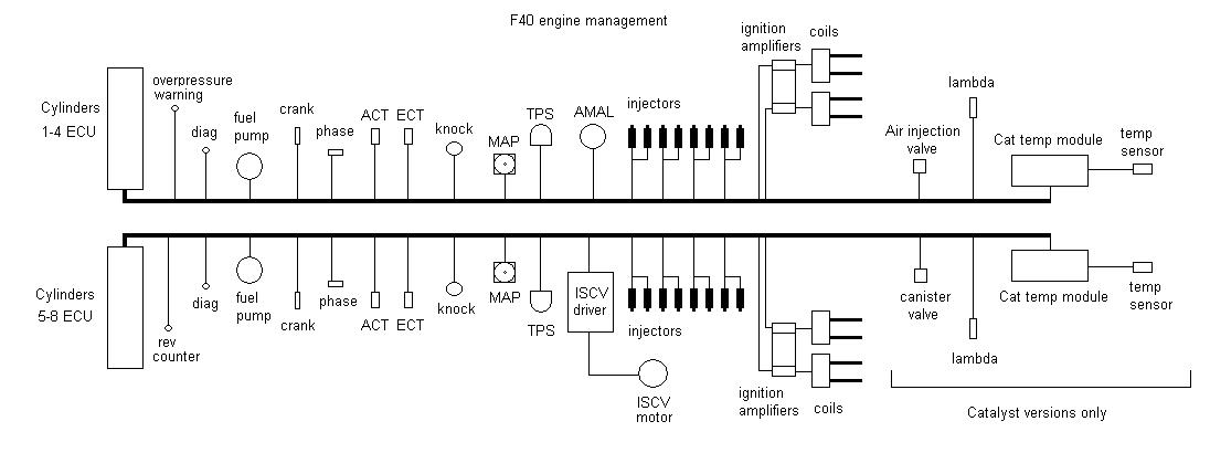
The two ecus are fixed to the engine bulkhead, inside the passenger compartment, behind the drivers and passengers seats. These ecus are a more complex design than the earlier 288 GTO and are more like the level 8. By having two ecus with totally separate sensors it is possible to keep running on one cylinder bank even when the other has developed a fault. Both ecus are exactly the same but the inputs and outputs vary between banks. To prevent the need for two different ecus they use the input on pin 13 as a bank position code. If the pin is grounded then it runs the program for bank 1-4 and if it is not connected then it runs the program for bank 5-8. Hence the ecus are interchangeable side to side for fault finding.
ECU Connections summary table :-
PIN |
RIGHT ECU BANK 1-4 |
LEFT ECU BANK 5-8 |
|---|---|---|
| 1 | GROUND | GROUND |
| 2 | LAMBDA SENSOR | LAMBDA SENSOR |
| 3 | CRANK SENSOR -VE | CRANK SENSOR -VE |
| 4 | CRANK SENSOR +VE | CRANK SENSOR +VE |
| 5 | PHASE SENSOR -VE | PHASE SENSOR -VE |
| 6 | KNOCK SENSOR | KNOCK SENSOR |
| 7 | N/C | N/C |
| 8 | DIAGNOSTIC INPUT | DIAGNOSTIC INPUT |
| 9 | N/C | N/C |
| 10 | ECU POWER RELAY (E) DRIVE | ECU POWER RELAY (C) DRIVE |
| 11 | SENSORS GROUND | SENSORS GROUND |
| 12 | BOOST OVERPRESSURE WARNING | REV COUNTER DRIVE |
| 13 | ECU POSITION INPUT - GROUND | ECU POSITION INPUT - N/C |
| 14 | N/C | FAST IDLE MOTOR SWITCH INPUT |
| 15 | MAP SENSOR | MAP SENSOR |
| 16 | AMAL BOOST VALVE | CARBON CANISTER PURGE VALVE |
| 17 | TPS | TPS |
| 18 | INJECTORS CYL 4 | INJECTORS CYL 8 |
| 19 | GROUND | GROUND |
| 20 | ECU +12V POWER | ECU +12V POWER |
| 21 | CATALYST OVER TEMP MODULE INPUT | CATALYST OVER TEMP MODULE INPUT |
| 22 | KNOCK SENSOR | KNOCK SENSOR |
| 23 | PHASE SENSOR +VE | PHASE SENSOR +VE |
| 24 | IGNITION MODULE -VE | IGNITION MODULE -VE |
| 25 | IGNITION MODULE +VE CYL 2&3 | IGNITION MODULE +VE CYL 6&7 |
| 26 | IGNITION MODULE +VE CYL 1&4 | IGNITION MODULE +VE CYL 5&8 |
| 27 | DIAGNOSTIC OUTPUT | DIAGNOSTIC OUTPUT |
| 28 | FUEL PUMP RELAY (A) DRIVE | FUEL PUMP RELAY (B) DRIVE |
| 29 | ECT | ECT |
| 30 | SENSOR 5V | SENSOR 5V |
| 31 | ACT | ACT |
| 32 | INJECTORS CYL 2 | INJECTORS CYL 6 |
| 33 | INJECTORS CYL 3 | INJECTORS CYL 7 |
| 34 | AIR INJECTION VALVE | FAST IDLE ECU DRIVE |
| 35 | INJECTORS CYL 1 | INJECTORS CYL 5 |
Pins 2,16L,21,34R are used only on models with catalytic converters.
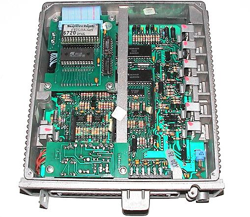
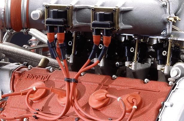
A normal IAW ecu is unable to drive twin coils as it only has one output stage so an extra circuit board is fitted internally with the extra components required on it (shown above near the 35 pin connector) and hand wired to points on the main pcb. Each ecu ignition output is then amplified by a pair of ignition modules mounted on a heatsink (one pair per cylinder bank) as below.
This is distributorless ignition with the pictures left coil firing cylinders 1&4 and right coil firing cylinders 2&3. You can also just see the 8 fuel injectors - 2 per cylinder. The ecu only has 4 injector drivers so the injectors are wired in parallel so they both inject at exactly the same time. This has got potential problems because if an injector should fail or stick closed, then that cylinder will only get half the required fuel. This will result in a lean mixture which could lead to a melted piston when on boost.
F40 ECU PROGRAM
The ecu program is contained in a 16K EPROM and is more like a Fiat or Lancia program than a Ford because of its ability to communicate with a diagnostic tester using serial data rather than flash codes. Not only can data be displayed, but ecu outputs can be activated. These tests are:
1. Run fuel pump for 10 seconds.
2. Pulse a fuel injector for 2.5mS every second for 10 seconds.
3. Fire an ignition coil every second for 10 seconds.
4. Drive the iscv motor open / closed twice for 2 seconds in each direction to check switch operation.
5. Open the amal valve for 10 seconds.
6. Drive the rev counter at 3000rpm for 10 seconds.
7. Flash overboost light on / off 10 times at 1Hz.
Catalytic Converter models also have:
8. Turn air injector on for 0.5 sec / off for 0.5 sec at 1Hz for 10 seconds.
9. Turn carbon canister valve on for 0.5 sec / off for 0.5 sec for 10 seconds.
Catalyst cars have a babyboard with the EPROM on containing extra RAM for the increased number of variables like the L8 Cosworth. It also does a more thorough self test at power up for RAM and EPROM checksum. If these fail the ecu will still operate but it will set an error flag which can be checked with diagnostics.
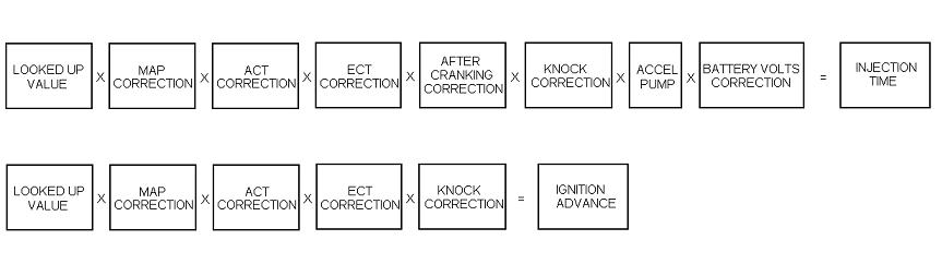
The rest of the program is very similar to the Cosworth but the main difference is the way the maps are referenced to throttle position rather than manifold pressure. The cosworth uses the 8 bit MAP a-d value corrected for atmospheric pressure and calibration pot to create a 16 bit look up value. The F40 uses the 8 bit TPS a-d value converted to a 16 bit value.
Fuel is a 16 rpm x 13 tps table while ignition is a 16 rpm x 8 tps table.
Using throttle position rather than MAP will create a sharper response and also allow more radical cam profiles to be used as a lumpy camshaft profile will create very poor vacuum on idle making mapping very tricky. The value looked up from the table must then be modified to allow for boost pressure etc so it represents actual air flow.
As standard the ecu has a soft cut rev limit of 7812rpm and a hard cut of 8012rpm. It has a boost control strategy like a P8 ecu with the boost cut threshold dependent on rpm rather than just a set value, and a transient 5.5psi overboost ability.